Vernier Calipers#
The Apparatus#
The instrument illustrated in Fig. 13 and Fig. 14 is a set of calipers. The calipers have two measurement scales, the main scale for large values, and the moveable Vernier scale for smaller increments.
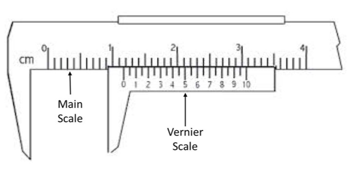
Fig. 13 Main and Vernier scales on a Vernier caliper.#
Focusing on Fig. 14, we can see:
The inside-measuring jaws used for measuring the inside length or diameter of a cavity
Clamp screw used on some of our calipers to hold the slider in place
The slider engraved with the Vernier scale that can slide along the main scale
Depth bar used to measure the depth of a whole or cavity
The main beam is the main structure of the calipers
Reference surface
Main scale, for coarse values
Vernier scale for fine values
The outside-measuring jaws used for measuring the outside length or thickness of an object or the diameter of a sphere or cylinder when placed between them
Step measuring face
Thumb clamp used on some of our calipers to hold the slider in place
While only the metric scales are shown in the drawing, the instrument does have both U.S. and metric main and Vernier scales. However, throughout the entire course, we will be using metric.
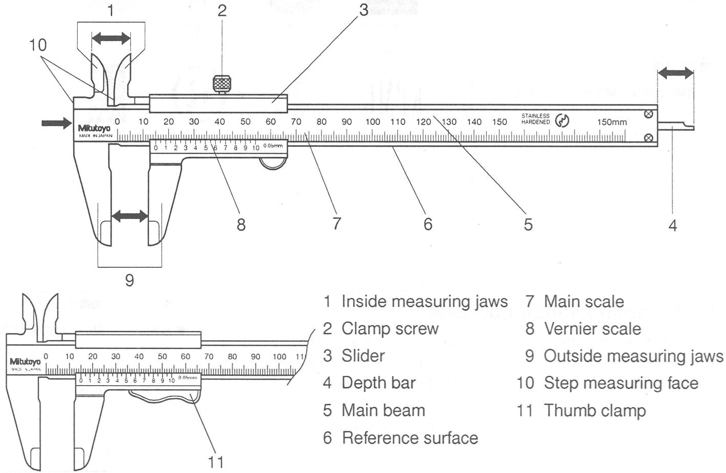
Fig. 14 A diagram showing Vernier calipers and their main measurement scales. The secondary insert shows other version of calipers we have with a thumb clamp instead of a clamping screw.#
Reading the Vernier scale#
Simplified example#
Vernier scales, as used on the calipers and on many other types of high quality measuring instruments provide a means of reading accurately fractions of a scale division that otherwise have to be estimated. In Fig. 15, we have two illustrated main scales with their Vernier scales. To measure, the three simplified steps are as in the figure.
Measure main scale based on the graduation where the zero-line on the Vernier scale coincides or is just to the right of the graduation on the main scale
E.g. 0.05 mm resolution example, the main scale reading is 9 mm since the zero line on the Vernier scale is just to the right of the 9 mm line on the main scale
Measure vernier scale when the graduation coincides with the graduation on the main scale
E.g. 0.05 mm resolution example, the Vernier scale reading is 0.15 mm since the .15 mm graduation line on the Vernier scale coincides to a graduation line on the main scale
Add the two scales together
E.g. 0.05 mm resolution example: 9 mm + 0.15 mm = 9.15 mm
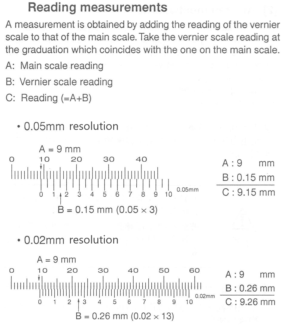
Fig. 15 A diagram showing two examples of reading measurements from Vernier calipers. Top) 0.05 mm resolution caliper example, Bottom) 0.02 mm resolution caliper example.#
Precautions#
For successful use of the calipers, Fig. 16 includes suggested techniques to ensure accurate measurement readings. Do’s are shown by the open circle, while don’ts are shown by a circle with a line through it.
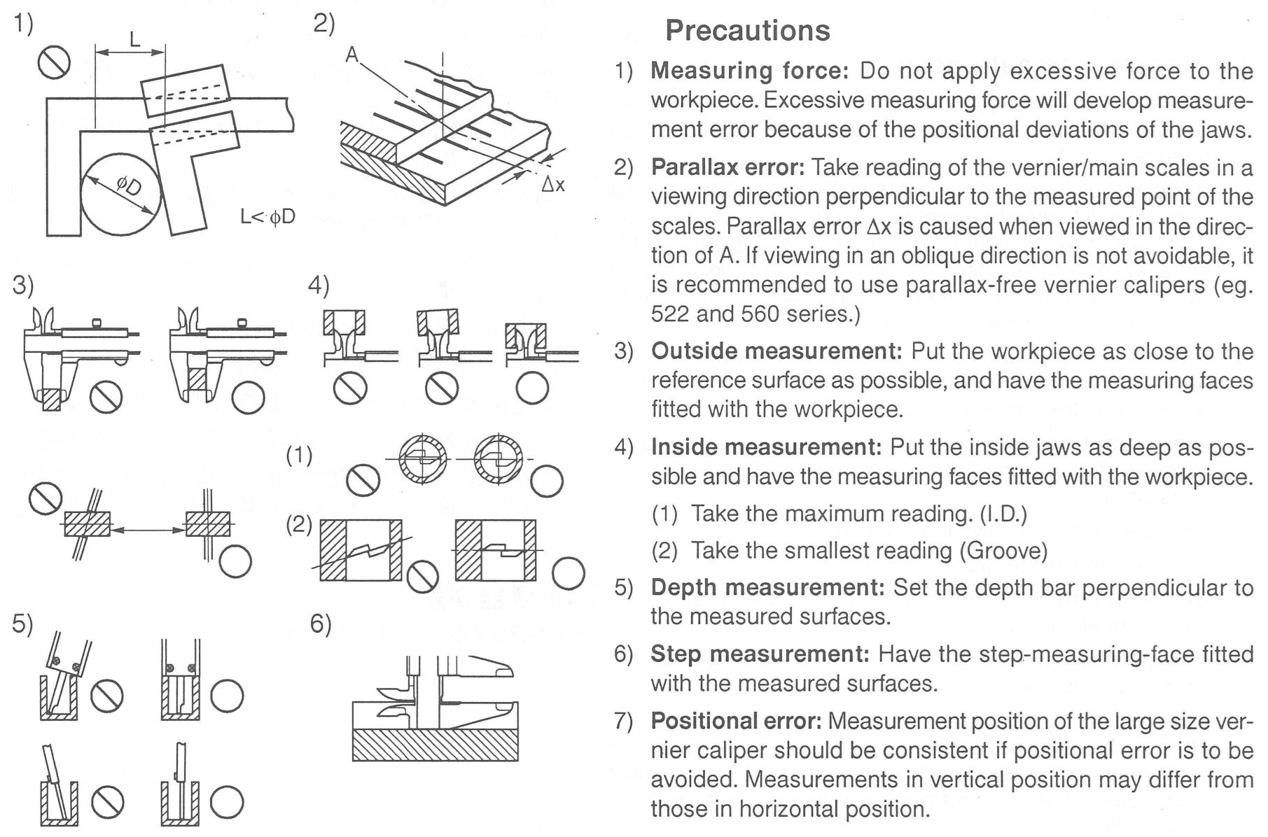
Fig. 16 A diagram showing precautions necessary for successful use of Vernier calipers.#
Web Example#
Use the following online resources to test yourself whether you are reading the Main and Vernier scales on the Vernier calipers correctly.
Simulated Vernier Caliper in the style of the calipers we use in lab
Simulated Vernier Caliper measurements of an object, simplified
Additional example with estimation#
Fig. 17 Repeated here for additional example measurement.#
If each division on the main scale is 1 cm (or 10 mm), then each division of the Vernier scale represents 1.0 mm. Physically, it is a 9 mm length divided into 10 equal parts. As an example, in the metric scale of Fig. 13 the zero of the upper or Vernier scale is between the 1 and 2 cm marks on the main scale. In this way, the Vernier scale is capable of interpolating to the nearest mm, the position of the Vernier zero mark on the main scale. In this example, the measurement is 1 cm + some number of mm. In order to determine the number of mm, we read the number on the Vernier scale whose line coincides with a cm division line on the main scale. (If the zero line of the Vernier is exactly on a division line of the main scale, then the measurement is exactly the main scale division.) In this example, the division of the Vernier scale that lines up with a main scale division is the 0.7 mm division. The measurement would be 1.17 cm. You might have the situation where there is no exact alignment. If that occurs, then you would estimate to the nearest 0.5 mm. For example, if the 7 mm division was slightly above and the 8 mm division was slightly below corresponding marks on the main scale, then the measurement would be 1.175 cm. Thus the Vernier scale is capable of estimating to the nearest 0.05 mm. The rule for this type of Vernier therefore is to read the number of whole main scale divisions below the zero line of the Vernier, and in the next place of decimals insert the number of the line on the Vernier scale which coincides with a main scale line.
The smallest quantity, which may be read without estimating, is known as the least count; this is 1 mm for the Vernier calipers illustrated. For the Vernier calipers you will use in the laboratory, the least count is 0.1 mm. In general, if the smallest division of the main scale of an instrument is \(M\) units, and the length of the smallest Vernier division is \(V\) units, then the least count, \(L\), is \(MV\). Also, since \(n\) Vernier divisions are equal in length to \(n-1\) main scale divisions,
or
and thus