Centripetal Force with Mass on Rotating Arm#
Background#
Acceleration is the measure of the rate of change of the velocity of an object by an external force. An object moving in a circle with radius \(R\) is always being accelerated, even if its speed does not change. Since velocity is a vector quantity, a centripetal force is required to change its direction. The radial centripetal acceleration, towards the axis of the rotational motion, has magnitude \(v^{2}/R\). The force producing this acceleration on an object of mass \(m\) will then have a magnitude of \(m v^{2} / R\).
In this experiment, this centripetal force is measured for an object in circular motion while varying the object’s speed. The centripetal force is supplied by a string pulling on the mass in an inwardly radial direction and is then measured by a force sensor (PASCO stated resolution of 0.002 N).
An object in uniform circular motion requires a centripetal or center-seeking force to change the direction of velocity vector. This centripetal force is related quadratically to the speed of the object, and inversely to its radius of curvature. As derived in your text, the magnitude of this force acting on an object of mass \(m\) with a radius of curvature \(R\), is given by
During each experiment the mass \(m\) and the radius \(R\) are fixed by attaching a small weight to a holder on a rotating arm as shown in Fig. 17. By measuring the force in the cable and the speed of the attached mass on the rotating arm, the mass \(m\) can be determined from a graph of force \(F\) vs. \(v^2\).
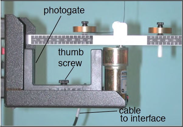
Fig. 17 Experimental Setup showing the rotating arm and the attached masses. The photogate to measure the speed is shown as well. The small white-ish pin attached underneath one of the mass holders is used to determine the speed \(v\) of the mass.#
In order to determine \(v\), the speed of the rotating mass, the rate at which the small pin attached underneath one of the two mass holders will move as it passes through the gap of the photogate is recorded. In order to do so correctly the width of the pin needs to be known to a very high precision.
In this experiment, the force needed to keep the mass at its predetermined radius is measured and plotted against the square of the speed of the mass at the same instant. You will repeat the experiment several times with different masses and at different radii.
Experimental Procedure#
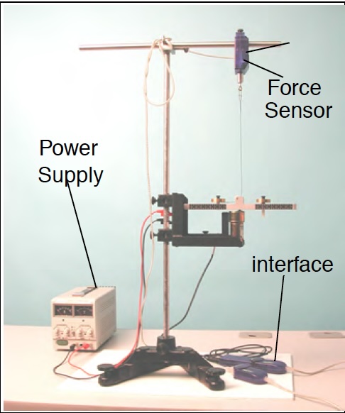
Fig. 18 Experimental Setup for the centripetal force experiment#
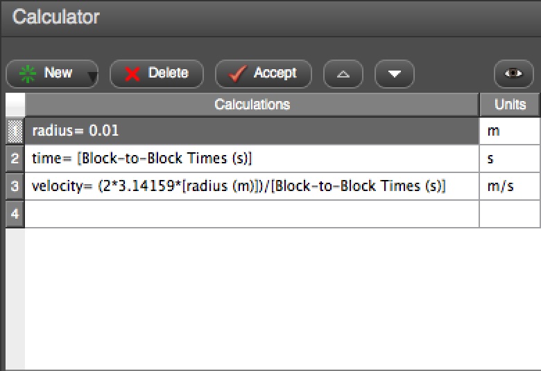
Fig. 19 Setup of the data acquisition system Capstone to measure the speed of the rotating masses. Make sure to adjust the value for the radius in this window to the actual value used in your experimental setup.#
You’ll run 6 cases, each with 3 trials:
2 radii: short, long
3 different applied masses: 0 g (empty holder), 5 g, 15 g
The experiment should already be setup for you as shown in Fig. 18 with masses attached to both the fixed and free mass holders.
Remove the free mass holder, and measure its mass with a triple-beam balance. Record this in your data sheet. Put the free mass holder back on the rotating arm.
Select Calculator in the menu on the left-hand side on the Capstone interface. This will open a window (example shown in Fig. 19) where you can update the radius to match the actual radius of your masses. NOTE: that the value for the radius will change in the experiment, and you need to adjust the value in Capstone when you switch to the new radius.
After setting the radius in the calculator, close the setup window by clicking on the Calculator button again.
There are graphs set up for you in Capstone plotting
\(F\) versus \(v^2\)
\(F\) versus \(v\)
Before data recording starts
Zero the force sensor with the zero button (physically on the force sensor) while the connecting cable is slack
Start the data acquisition on Capstone by pressing the Record button. You should notice that the program will start to record values.
Slowly increase the voltage on the power supply from 0V to 10V over the course of about 30 seconds. The metal arm will start to rotate and you will notice the graphs display the data as it is collected. Do not exceed 10 V and turn off the data acquisition (by pressing the Record button again) before returning the power supply to zero.
Once you have finished your run, fit a line to your \(F\) vs. \(v^2\) graph. Select the fit box. In the Curve Fit Editor, lock the intercept \(b = 0\). Notice the change in \(m\) when you lock \(b\). Record the slope \(m\) in the Data Table.
Fit a Quadratic curve to your \(F\) vs. \(v\) graph. Fit the curve \(F=A v^2\) by locking B and C to zero. Notice the change in A when you lock B and C. Discuss why B and C should be zero. Record A in the Data Table.
Repeat the measurement two more times. Calculate the average fit parameters for the three runs.
Determine \(m\), the value of the rotating mass from both graphs and note the result in your data table. Explain how you determine the value from your data.
Repeat the experiment with two more masses at the same radius \(R\). Please call for help in setting up the experiment with the new settings. Note all results in your data table. Discuss already why you also need to adjust the mass on the fixed mass holder and not just on the free mass holder.
Repeat the experiment with the same 3 masses as above at a different radius \(R\). Note all results in the data table.
Data Analysis#
In this experiment, you measure the centripetal force with two different radii and three different applied masses for a total of six cases. Each case is repeated for three trials. The curve fitting to determine the mass is performed with the Capstone program.
For each case, construct a table with a row for each trial including:
the radius
the applied mass plus the mass of the holder as measured earlier
fit parameter \(A\) from the \(F\) vs. \(v^2\) (linear fit)
the mass determined from the centripetal \(F\) vs. \(v^2\)
the difference between the applied mass plus holder and the determined mass from \(F\) vs. \(v^2\)
fit parameter \(m\) from the \(F\) vs. \(v\) (quadratic fit)
the mass determined from the centripetal \(F\) vs. \(v\)
the difference between the applied mass plus holder and the determined mass from \(F\) vs. \(v\)
your estimate of the uncertainty in the radius (i.e. \(\text{radius} \pm \text{how much?}\))
the uncertainty in the mass from the centripetal force due to your estimated radius uncertainty (Point to consider: how much does the derived mass change if you change your value for radius in Capstone calculator by the amount of your estimated radius uncertainty?)
From the data collected in the six cases you ran, determine the values of the masses \(m\), using the given value for the radius \(R\), as well as the related uncertainties.
Post-Lab Submission — Interpretation of Results#
Make sure to submit your finalized data table (Excel sheet)
Do the graphs display the expected behavior?
Discuss your results. Do your experimentally determined masses ± uncertainty agree with the actual mass of the applied masses plus mass holder?
Discuss uncertainties (sources of, how do they affect your final mass values; what would have the largest affect?).
What is the precision of your equipment?
What are possible systematic errors for today’s experiments?
Why there should be the same mass on the fixed mass holder as compared to the free mass holder?