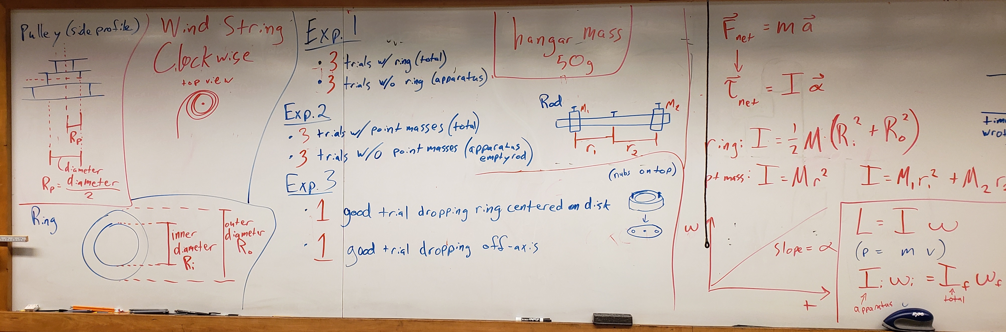
1171L-ONLY | Rotational Dynamics with Moment of Inertia & Angular Momentum
Background
● Background Overview
The motion of an object can be divided into two, completely independent parts: the linear (translational) motion of the center of mass and the rotational motion of the object around an axis through the center of mass. The linear motion is explained by Newton’s 2nd Law of motion: a net force acting on an object of mass will cause the object to experience a linear acceleration given by
Rotational motion can be described in a very similar manner, but the quantities involved need to be changed to rotational quantities. These quantities are described and explained in detail in the following paragraphs.
● Moment of Inertia
In rotational motion the moment of inertia (usually denoted by ) takes the role of mass. An object with a large value of will be reluctant to change its rotational motion. Just as mass this quantity is a scalar, meaning that it has no direction. The moment of inertia of a system of objects can be determined easily by adding the moment of inertia of each of the different components making up the entire system. The moment of inertia depends not only on the mass of the object but also on how the mass is distributed with respect to the axis of rotation. The further the mass is away from the axis of rotation, the higher the moment of inertia will be. For a point mass (an object that can be considered small with respect to its distance from the axis of rotation) the moment of inertia is defined as
where is the mass of the object and is the distance of the object from the axis of rotation.
The calculation of the moment of inertia for more complex objects is a rather straightforward process, but can be very tedious. In most cases simple expressions can be found to calculate the value of . The list below gives the moment of inertia for a few objects used in this lab:
Multiple point masses of mass and radius considered as a single object, the moment of inertia can be represented as the sum of point masses:
A thin rod of mass and length rotating about an axis through its center:
A solid disk of mass and radius rotating about an axis through its center:
A thin-walled ring of mass and radius rotating about an axis through its center:
A thick ring mass and inner radius and outer radius rotating about an axis through its center:
● Torque
A force by itself is not enough to determine whether an object will start to rotate (just think about how a force that is applied to the hinges of a door will not rotate the door). Instead we define a new quantity, called torque , which combines the force and the distance from the axis of rotation (also called the lever arm). This quantity is a vector quantity, meaning that it does have a direction
Here denotes the lever arm (directed outward from the center) and is the component of the force perpendicular to the lever arm.
● Newton’s 2nd Law for Rotational Motion
With the above definitions we can now formulate a rotational version of Newton’s 2nd Law. An object with moment of inertia will experience an angular acceleration , if a net torque acts on it
● Calculating the Moment of Inertia
One can use Newton’s 2nd Law for Rotational Motion to calculate the moment of inertia of an object from the angular acceleration and the net torque acting on the object.
The simplified sketch in Figure 1 shows the setup used in this lab. The net torque acting on the pulley can be written as
where is the tension in the string and is the radius of the 3-step pulley. Since the tension is not known it has to be determined from the linear acceleration a of the hanging mass, using the net force acting on the mass (see force diagram in the sketch):
In addition the linear acceleration is related to the angular acceleration by
Using this set of equations one can now solve for the moment of inertia, ,
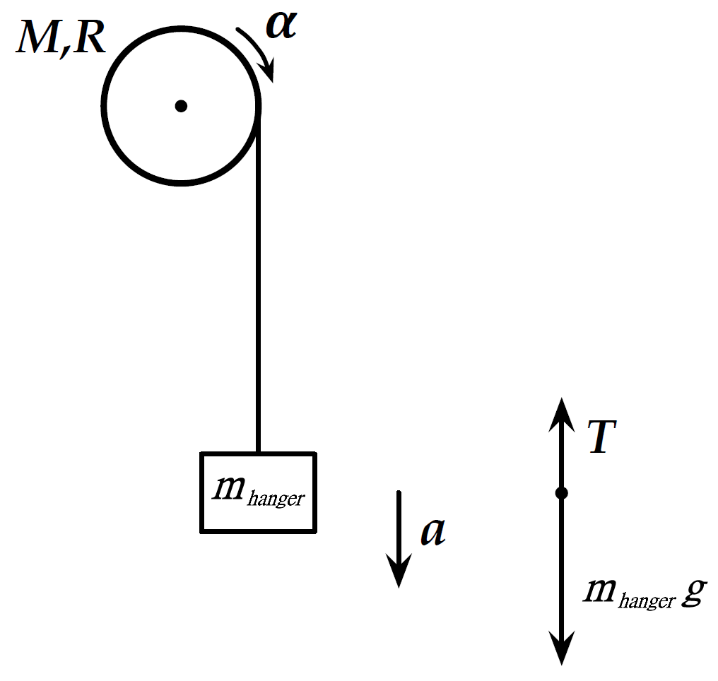
Figure 1:Left: Sketch of a pulley of mass and radius being accelerated by a hanging mass . Note that the pulley in the lab is actually horizontal, but is drawn vertically here for simplicity. Right: Force diagram for the hanging mass .
● Angular Momentum
A similar derivation as above can be used to define the quantity of angular momentum from the definition of linear momentum ()
Angular momentum is conserved (meaning it will not change its value) if there is no external torque acting on a system
This can be used to determine the angular velocity of a system if the moment of inertia changes
THE PARALLEL AXIS THEOREM is used to calculate the moment of inertia of an object of mass rotating about a rotation axis that does not pass through the center of mass (e.g. the ring on top of the apparatus is off center). The moment of inertia for the axis is
where is the moment of inertia about an axis through the center of mass parallel to the rotation axis. The distance between the parallel axes is . In the Conservation of Angular Momentum experiment you drop the ring on the rotating apparatus. Although you try to drop the ring centered on the axis of rotation, it often lands off center. You will run a case where you try to center it, and then another case where you purposefully drop it off center.
Experimental Procedure
● Preliminary Setup
The lab today makes use of a rotary sensor, which is able to detect and measure angular displacement, angular velocity, and angular acceleration. This Rotary Motion Sensor (RMS), with a stated uncertainty of 0.09°, is attached to a vertical rod and has a 3-step pulley affixed to its axle (see Figure 2). Objects with different moments of inertia can be mounted onto the 3-step pulley and their rotational motion be measured. A second, black pulley (called a Super Pulley) is attached at an angle to the RMS to allow a string to spool off the 3-step pulley as shown in Figure 2. A weight hanger of known mass is attached to the free end of the string and provides an accelerating torque to the 3-step pulley and therefore to the object mounted on it.
The objects to be mounted are either a rod with point masses in Figure 3 and a disk with an accompanying thick ring in Figure 4.
In this lab, you will run a Moment of Inertia experiment and an Angular Momentum experiment. You will first determine the angular acceleration from a graph of angular velocity vs. time using data recorded with the RMS. The data will be collected and analyzed in Capstone. The moment of inertia of both two point masses and a thick ring will be determined from those experimental angular acceleration values. Finally in the Angular Momentum experiment, you will verify the validity of angular momentum conservation in an inelastic collision, and consider the parallel axis theorem.
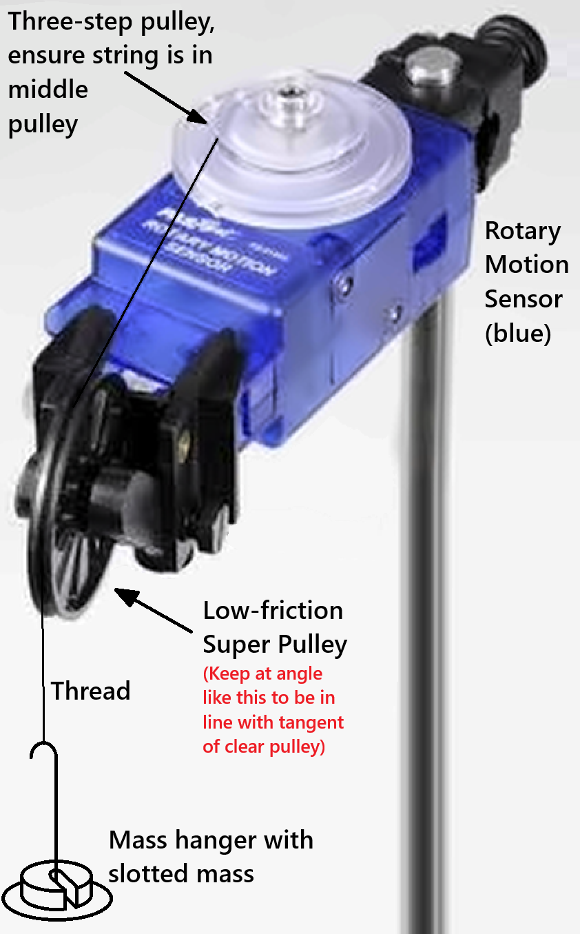
Figure 2:Rotary Motion Sensor (RMS) with 3-step pulley (transparent) and Super Pulley (black). Super pulley should be at an angle to ensure the thread lines up tangent to the 3-step pulley.
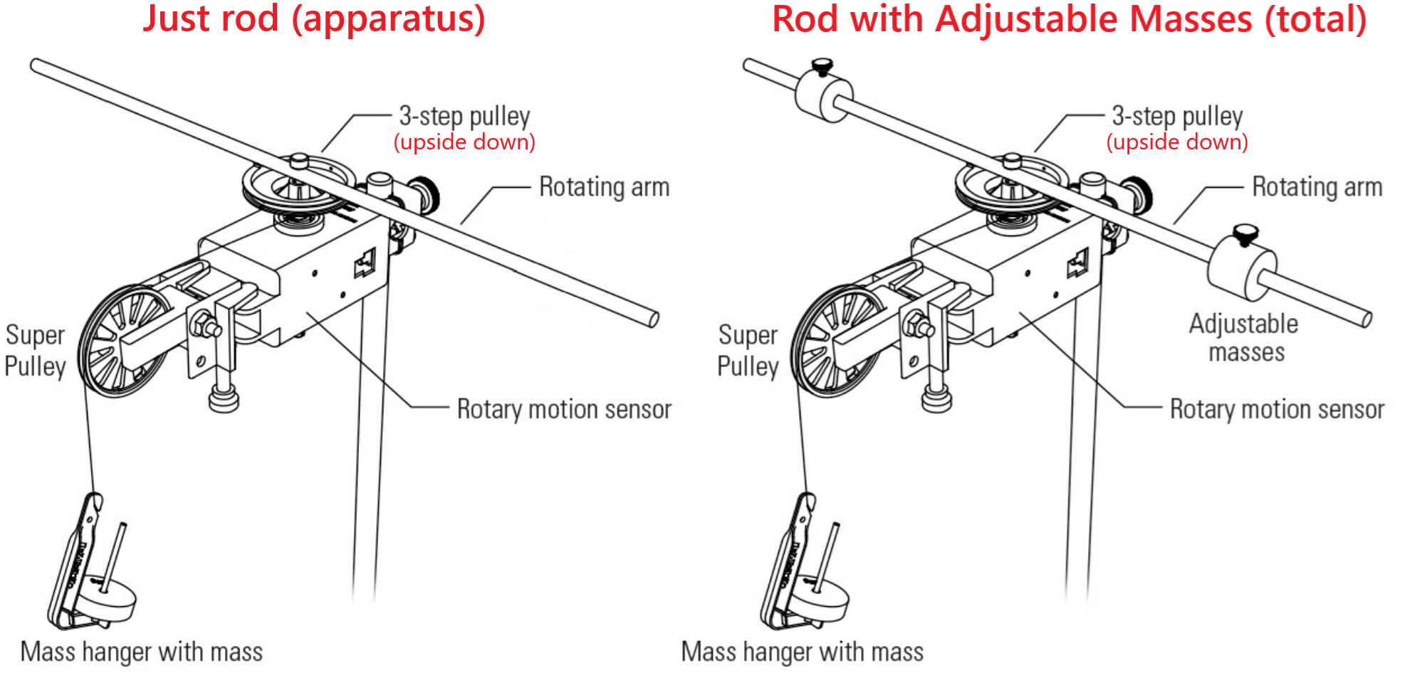
Figure 3:Sketch of the RMS apparatus setup for “point masses” on a rotating rod. Left) Just apparatus (i.e. rod), Right) total from the apparatus and point masses combined.
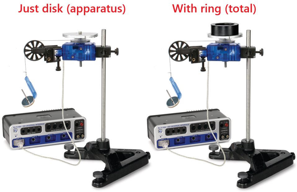
Figure 4:Experimental setup of the RMS apparatus with disk alone (left) and with disk and ring mounted (right). The setup varies slightly from the one used in the lab.
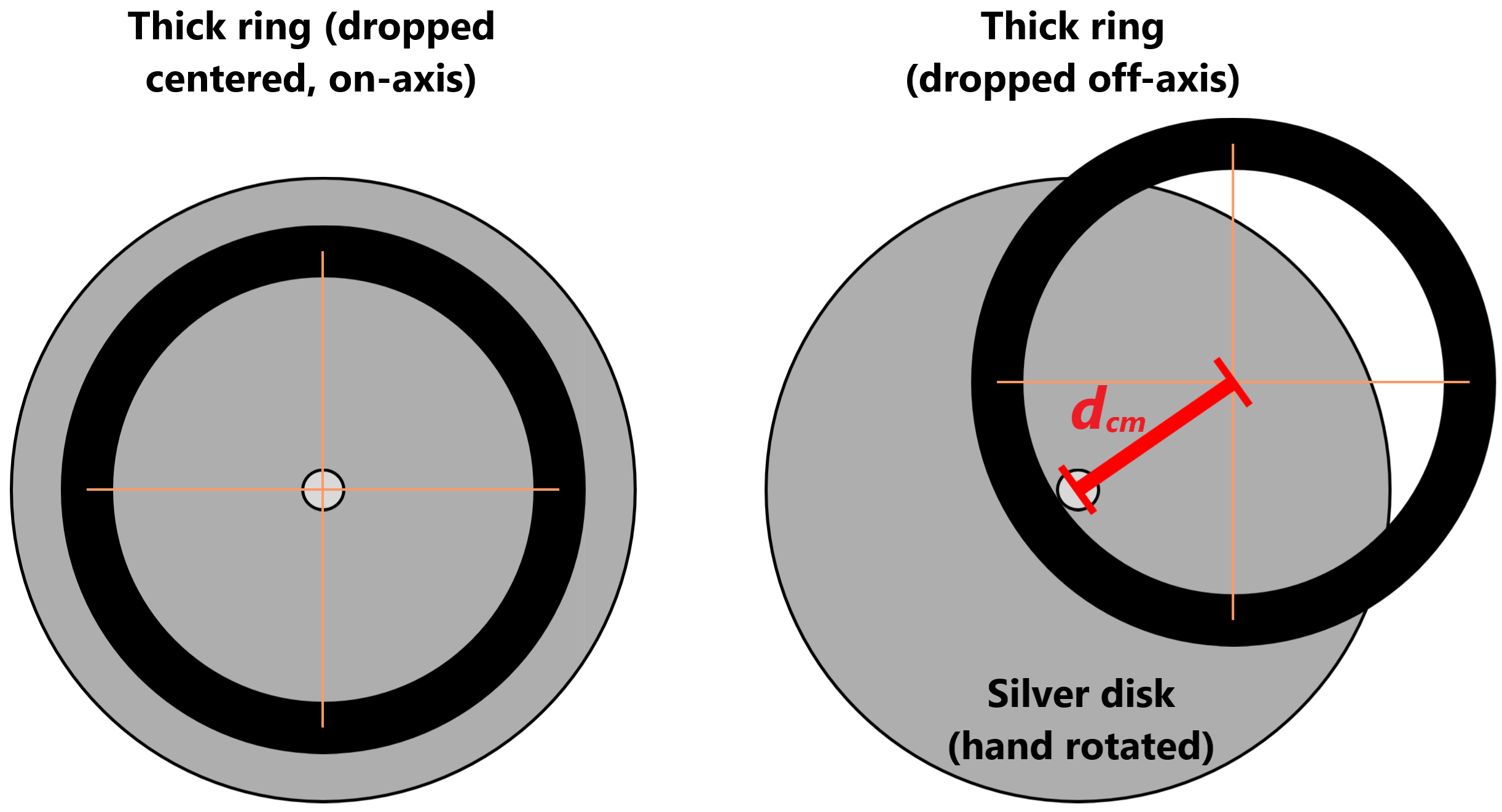
Figure 5:Experimental setup of the Conservation of Angular Momentum experiment with *collisions: Left) Thick ring dropped on-axis, Right) Thick ring dropped off-axis.
● Part I --- Moment of Inertia of Two Point Masses
Create a data table to find including:
the masses and
the radii and
the expected moment of inertia of the point masses together
Create a data table to find including:
the hanging mass
the radius of the pulley
the total experimental angular acceleration and moment of inertia of the apparatus with masses (pulleyRodPointMasses)
the experimental angular acceleration and moment of inertia of just the apparatus (pulleyRodOnly)
the experimental moment of inertia of just the point masses .
Please call the lab instructor for assistance if not yet set up:
Mount the rod onto the pulley of the RMS by removing the screw, remounting the clear RMS pulley with the key/slot in the widest-at-top orientation (see Figure 3), and placing the rod onto the notches of the clear RMS pulley, then using the longer screw on the rod to tighten everything back together.
Determine the masses of the two brass weights (with screws) and note the result as and in your Data Table.
Mount the masses into the end of the rod and fasten them with the screws. Measure the distance of the center of the masses from the center of the rod. Note the results as and in your Data Table.
Calculate the expected moment of inertia of just the two points masses, using (2) and (3) given in the Introduction. Note your result as in your Data Table.
Note the mass of the hanger as in your Data Table.
Using the calipers measure the radius of the middle pulley of the RMS and note your result in your data table. NOT THE EDGES, MAKE SURE THE CALIPER FITS IN THE GROOVE. THERE IS AN ADDITIONAL EMPTY CLEAR PULLY IN YOUR BOX YOU CAN MEASURE FOR EASE OF USE (and for the angular momentum lab later on).
Wind the string, with the mass hanger attached, clockwise onto the middle pulley of the RMS. You need to make sure that the string is wound nicely onto the clear middle pulley of the RMS, leaves tangentially from the clear pulley straight in line with and over the black Super Pulley (reminder, see off angle orientation noted in Figure 2).
Measure the angular acceleration of the whole system (i.e. of the two masses plus the apparatus):
Make sure that in Capstone you have a graph of angular velocity (-axis) vs. time (-axis) open; same plot as seen in Figure 6.
Before releasing the mass hanger press the Record button on Capstone.
Release the mass hanger and observe the recorded data points/graph.
Press the Record button again right before the string is completely unwound from the pulley to stop recording any more data points.
Discuss (among yourselves and with your instructor) the resulting graph before continuing.
Using the Fit option in Capstone, fit a straight line (linear fit) to the data, in the region where the system is accelerating (highlight the data region in the graph you want to fit).
The slope of this graph is the angular acceleration .
Note your result in your Data Table.
Calculate the moment of inertia of the apparatus plus the two point masses, using (14) given in the Introduction. Note your result as in your Data Table.
Remove the two point masses from the apparatus and repeat the above steps to determine the moment of inertia of the apparatus without the two masses. Note the result as in your Data Table. Please note that you need to again discuss the collected data points/graph with your lab instructor.
To determine the moment of inertia of the two point masses subtract from . Note your result as in your Data Table.
Repeat the above measurements for a total of 3 trials.
Calculate averages and standard deviations for the moments of inertia.
Compare the difference between your expected value and the experimental value with the standard deviation treated as your uncertainty range.
● Part I --- Moment of Inertia of a Thick Ring
Create a data table to find including:
the ring mass
the inner and outer radii of the ring (, )
the expected moment of inertia of the ring
Create a data table to find including:
the hanging mass
the radius of the pulley
the experimental angular acceleration and moment of inertia with the apparatus with the ring (pulleyDiskRing)
the experimental angular acceleration and moment of inertia of just the apparatus (pulleyDiskOnly)
the experimental moment of inertia of the ring
Please call the lab instructor for assistance:
Mount the disk onto the pulley of the RMS by removing the screw and rod, flipping over and remounting the clear RMS pulley with the key/slot lined up and in the smallest-at-top orientation (see Figure 2 & Figure 4), and placing the disk onto the square of the clear RMS pulley, then using the shorter screw to tighten everything back together.
Determine the mass of the ring and note the result as in your data table.
Measure and record the inner and outer radii of the ring, using the calipers. Note the result as and in your data table.
Calculate the expected moment of inertia of the ring, using (7) given in the Background. Note your result as in your data table.
Place the ring onto the disk, which should already be mounted on the Rotary Motion Sensor (RMS). The two pins of the ring should fit into the two holes on the disk.
Note the mass of the hanger as in your Data Table.
Note the radius of the middle pulley of the RMS in your Data Table (use the result from the previous case).
Wind the string, with the mass hanger attached, clockwise onto the middle pulley of the RMS. You need to make sure that the string is wound nicely onto the clear middle pulley of the RMS, leaves tangentially from the clear pulley straight in line with and over the black Super Pulley (reminder, see off angle orientation noted in Figure 2).
Measure the angular acceleration of the ring plus the apparatus (i.e. the disk and the RMS).
Make sure that in Capstone you have a graph of angular velocity (-axis) vs. time (-axis) open.
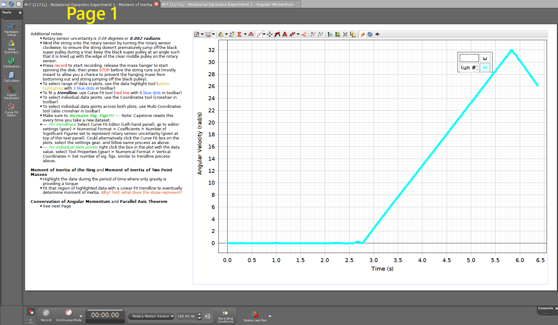
Figure 6:Example of Page 1 in today’s Capstone file for both ring and point mass moment of inertia cases. Review notes in the text box to assist in your data taking and analysis.
Before releasing the mass hanger press the Record button on Capstone.
Release the mass hanger and note that the recorded graph is a straight line.
Press the Record button again right before the string is completely unwound from the pulley to stop recording any more data points.
Using the Fit option in Capstone, fit a straight line (linear fit) to the data, in the region where the system is accelerating (highlight the data region in the graph you want to fit).
The slope of this graph is the angular acceleration .
Note your result in your Data Table.
Calculate the moment of inertia of the apparatus plus the ring, using (14) given in the Introduction. Note your result as in your data table.
Remove the ring from the apparatus and repeat the above steps to determine the moment of inertia of the apparatus without the ring. Note the results as and in your Data Table.
To determine the moment of inertia of the ring, subtract from . Note your result as in your Data Table.
Repeat the above measurements for a total of 3 trials.
Calculate averages and standard deviations for the moments of inertia.
Compare the difference between your expected value and the experimental value with the standard deviation treated as your uncertainty range.
● Part II --- Conservation of Angular Momentum
Create a common data table including and .
Create a data table with a row for each trial including
the initial angular velocity, ,
the final angular velocity, ,
the initial angular momentum, ,
the final angular momentum, ,
the change in angular momentum, .
Please call the lab instructor for assistance:
Change out the current clear RMS pulley (with a string and hanging mass) for the empty RMS pulley.
Mount the disk onto the empty RMS pulley.
Copy your experimental value for the moment of inertia of the apparatus (i.e. just the disk) from the first experiment for use here (reminder, you can easily reference cells in Excel).
Copy your experimental value for the moment of inertia of the ring plus apparatus from the first experiment.
Hold the ring with the pins facing up just above the center of the disk.
Practice the drop a few times before continuing:
Give the disk a quick spin with your hand.
Hold the ring a few millimeters above the spinning disk centered on the axis of the disk.
Drop the ring onto the spinning disk, so that the ring is centered on the disk (see Figure 5-left).
Measure the angular speeds and (before and after dropping the ring onto the disk):
Switch to page 2 in your Capstone file. You shouce have a graph of angular position (-axis) vs. time (-axis); see Figure 7.
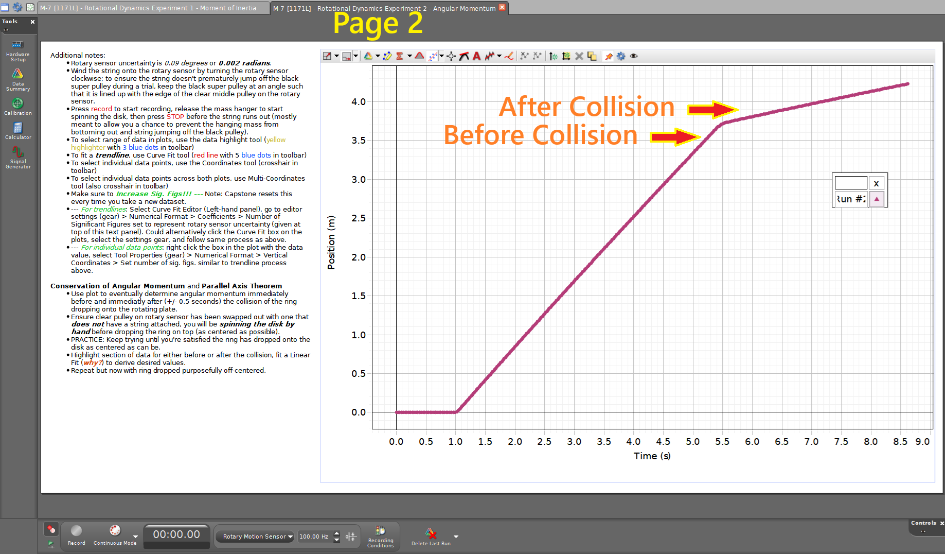
Figure 7:Example of Page 2 in today’s Capstone file for the angular momentum experiment. Review notes in the text box to assist in your data taking and analysis. Note the region in the plot before and after the collision.
Press the Record button in Capstone.
Give the disk a spin with your hand and notice the angular position change.
Ensure you’ve recorded a few seconds of data, then drop the ring as centered as you can onto the disk.
Press the Stop button after collecting a few more seconds of data.
Using the Highlight Data tool, highlight first the data region immediately before the collision; .
Using the Curve Fit tool, fit a straight line (linear fit) to that highlighted data, and record the slope as initial angular velocity .
Shift your data hightlight box to immediately after the collision; again covering .
The curve fit should update, and you can record the slope as final angular velocity .
Calculate the angular momentum of the appartus before the ring is dropped onto the disk. Note your result as in your Data Table.
Calculate the angular momentum of the disk-plus-ring system after the ring is dropped onto the disk. Note your result as in your Data Table.
Compare the difference between your expected value and the experimental value, also compare with a percent difference.
Parallel Axis Theorem test:
Run an additional test of the angular momentum part where you drop the ring to purposefully be off center (see Figure 5-right).
Measure the off-center distance when the ring is all the way against the main axis of rotation of the metal plate (i.e. inner edge of the ring against the screw).
Calculate the updated moment of inertia of the ring using the parallel axis theorem, (18).
Spin the disk as fast as possible and drop the ring off center to the point where it ends up against the screw, akin to what you just measured for .
Record both the initial and final angular velocities.
Calculate both the initial and final angular momentum.
BEFORE CLOSING CAPSTONE:
BEFORE LEAVING LAB:
Post-Lab Submission --- Interpretation of Results
This week’s lab is built of essentially two different, but still related to rotational motion, experiments. To assist in your analysis and writeups, the suggested talking points below are broken up into the Moment of Inertia and Angular Momentum parts of the lab. You will still have single document for error analysis and single document for results as assignments in Blackboard.
● Finalized Spreadsheets
Make sure to submit your finalized data table (Excel sheet).
Please include relevant screenshots of your Capstone plots including:
Moment of Inertia:
1 plot of Angular Velocity vs. Time for disk (apparatus)
1 plot of Angular Velocity vs. Time for disk plus thick black ring (total)
1 plot of Angular Velocity vs. Time for empty rod (apparatus)
1 plot of Angular Velocity vs. Time for empty rod plus point masses (total)
Angular Momentum:
1 plot of Angular Position vs. Time showing changing slope before and after collision (dropping of ring)
● Moment of Inertia Post-Lab
In a paragraph, summarize your error analysis. Be both qualitative and quantitative.
What are your measurement uncertainties for each experiment?
What are possible systematic uncertainties for each experiment?
How do these uncertainties affect your final results for ?
In a paragraph, summarize the results you have determined in each case. Consider:
Part 1: How do the values of both the ring’s and two-point masses’ measured compare to the “predicted (from geometry)” value? Treating your standard deviations as your uncertainty, do your results span the difference between experimental and theoretical, thereby agreeing?
Part 1 (empty rod): In the part of the experiment measuring the moment of inertia of the rod apparatus without the weights, notice that the rod turns quite fast and that the angular acceleration decreases as the speed increases (see plot in Capstone). Why does this happen?
● Angular Momentum Post-Lab
In a paragraph, summarize your error analysis. Be both qualitative and quantitative.
What are your measurement uncertainties for each experiment?
What are possible systematic uncertainties for each experiment?
How do these uncertainties affect your final results for ?
In a paragraph, summarize the results you have determined in each case. Consider:
Part 2: Is angular momentum conserved? What might cause any discrepancies in the conservation of angular momentum?
Part 2: What is the effect of dropping the ring off-center? Is conserved when considering the off-axis portion?
The Whiteboard